TERMINOLOGY
TABS :
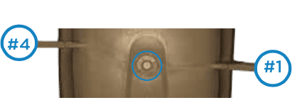
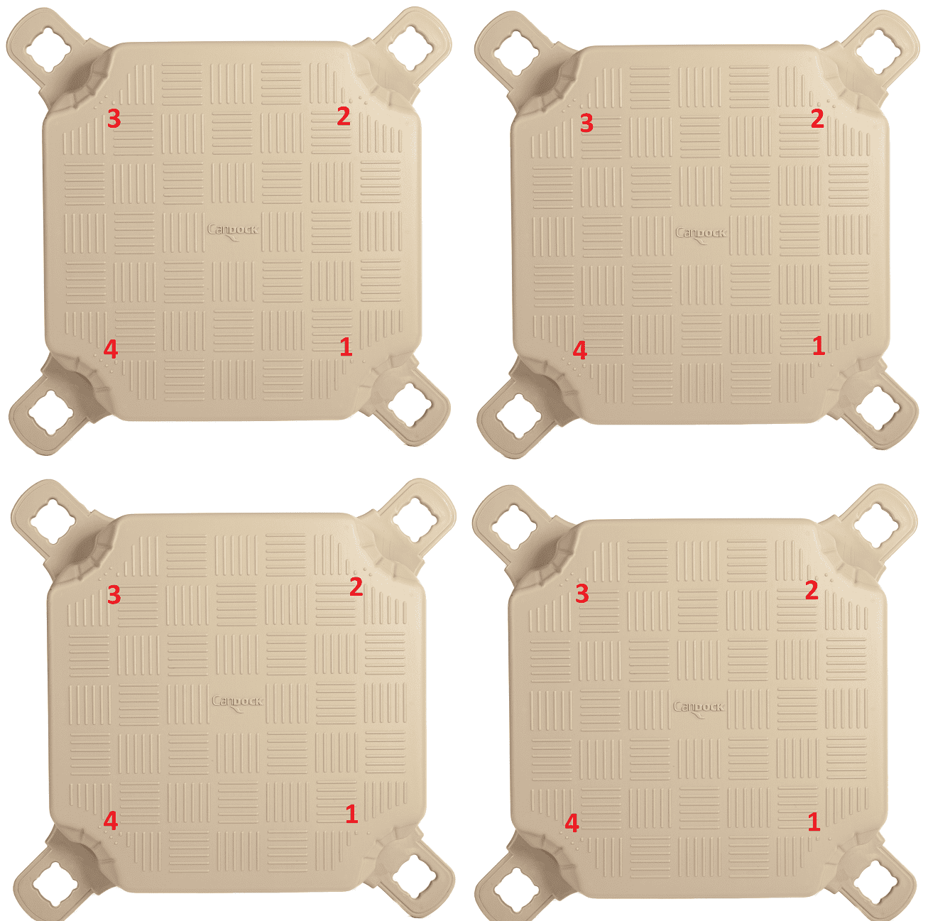
Prominent grooved parts of the cube, which are located at different heights on each of the 4 corners of the “cube” (tab #1 to #4, #1 being the lowest and #4, the highest). These tabs are an integral part of the Candock system. When ralied in groups of 4, the cubes create a larger square. At the center of this square, 4 different tabs overlap each other. These tabs form a single opening and are meant to be coupled with our CANDOCK SLIDING NUT and G2 or G1 CONNCETING PIN to form a unique structure.
PLUGS :
These watertight plugs are always found on the side of the cube that isbetween tab # 1 and # 4. These plugs, made of breathable material on the G2 line, act as pressure release valves thus preventing any cube deformation which is due to temperature or altitude.Furthermore, these plugs prevent any condensation inside the cube. On the other hand, some older prodcutions of the G1 line are not equipped with our most advanced breathable plugs, they are simply scealed with regular blag plugs.

ASSEMBLY PROCEDURE
With the use of the provided tools, proceed following these few steps:
PRIOR TO INSTALLATION
*During the installation of a dock, always have the plugs oriented towards the shore. This orientation will simply use less CANDOCK SPACERS and will improve the aesthetic of your dock. (*If your configuration is meant to go along the shore line instead of off-shore, align plugs towards the shortest side of your dock)
**Always make sure to regroup 4 different tabs height to complete your assembly. Make sure they are in their pre-destined position and that none of these are wrongly placed.
***Preassemble the dock in larger sections directly on the ground. When in water, prepare the missing units of G2 CONNECTING PINS and CANDOCK SLIDING NUTS and position on the corresponding side of each sections. This will help you save time.
ORIENTATION OF TABS

CONNECTING G1 CUBES TO G2 CUBES
Before starting, identify the actual orientation of your existing dock ( G1 or G2 ). Usually, the plugs should be oriented toward the shoreline as it creates a more aesthetic layout. Pretending it is the case in every situations, the following instructions will be based on such premise. If they happen to be oriented differently, simply remember the following trickery. The 2 product generations will have to be oriented in “opposite” directions. Proceeding in such way will simply garantee a seamless connection of both walking surfaces.
1- Place the G2 cube close to its final position while making sure that the plug of the new G2 cube will be facing directly against the plug of the G1 cube.
2-Locate the lowest tab available where the 3 other cubes and the G2 cube are “meeting” each other.
3-Insert the black sliding nut on this lowest tab.
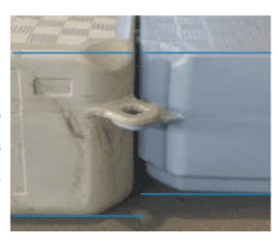
4-In order to create an seamless junction between the 2 generations of cubes ( on their SURFACES ), insert regular spacers in-between the gaps as shown on the image. Indeed, the tabs heights
on both generation are not the same and there is 2 “empty”
spaces that needs to be filled when joining cubes together.
5-Complete installation by screwing the needed connecting pin in place ( * note that it is mandatory to use G2 pins when connecting the 2 generations of product as they simply fit better. For that matter, I included 1 unit of those G2 connecting pin.)
LIMITATION
-Merging the product generations is limited to a width of 5 to 6 cubes maximum. This is due to the slight difference in overall dimensions between the 2 generations.
-It is difficult to randomly mix the 2 generations because of the relative heights of the tabs.
*Note that the height difference of the 2 generations is transfered to underneath the dock. Gently sloppingto the water, the first G2 cubes that will be connected to the G1 will be partially touching the water surface.


